1. It's never been easier to start a hardware company. The Internet of Things (IoT) phenomenon—touted by many as the future of embedded computing—is now seen as an amalgam of affordable hardware and software platforms. At the same time, however, software complexity makes the IoT design process a classical case of survival of the fittest.
    The IoT design is not a one-size-fits-all premise because the diversity of sensors and connectivity solutions require a new design thinking. Moreover, the IoT projects are typically known to be high-performance, low-cost and low-power, and all of these characteristics are intertwined with the embedded software work one way or the other.
    Take the high-performance and low-cost factors, for instance, which imply that the reuse from the previous projects is limited and software engineering teams won't expand proportionately. So, instead of growing the software team and expanding the project cost, IoT product developers are looking to a new generation of tool-chains that help them accomplish greater software productivity.

    Figure 1: Across-the-board software tool-chain is crucial in the heterogeneous IoT designs. (Source: Atmel)
    The IoT design work is a walk on the tightrope also because there are so many moving parts, and design engineers can't afford to build a subsystem and see later if it works. The start-overs not only add to project cost, they also bring severe time-to-market constraints to the heterogeneous world of IoT design.
    So the IoT design recipe—starting with data capture from sensors to data analytics inside the cloud—requires design validation long before engineers commit silicon to an IoT product. Not surprisingly, therefore, an end-to-end hardware and software platform along with a suite of connectivity solutions is critical in dealing with complexities that come with the challenge of connecting a large number of devices in a seamless manner.
    The article delves into major software challenges in the IoT design realm and shows how the right choice of tool-chains can help deal with the embedded design challenges. It focuses on three key areas of the IoT software ecosystem and offers insight on how to execute the software work in an efficient and cost-effective manner.
    1. Software Complexity
    The hardware-software work allocation generally comes down to a 40:60 split in the embedded design projects. However, in the IoT design projects, there is even a greater tilt toward software ecosystem.
    The IoT developers are migrating from 8-bit and 16-bit microcontrollers to 32-bit devices in order to accomplish higher performance and enhanced functionality in areas such as connectivity, graphic display and cloud computing.
    And that calls for a new software playing field that can efficiently execute communication and cloud computing protocol stacks. Then, there are tasks like the real-time sampling of sensor data, device configuration, security keys, apps, data analytics and more.
    Furthermore, a lot of software in the IoT designs is related to communication stacks like TCP/IP and security libraries such as SSL and TLS; these software components are written to comply with specific standards. These software components have been written before, time and time again, and it makes little sense for an IoT developer on a tight deadline to re-implement them instead of using the existing software.
    In fact, creating this software from scratch risks introducing issues that have already been found and fixed in the existing implementations.

    Figure 2: A complete software ecosystem is vital in confronting the complexity of IoT designs. (Source: Atmel)
    Tips and Tricks:
    • Integrated development environments (IDEs) are the first line of defense in coping with the software complexity that comes with ever more functionality implemented in the IoT applications.
    • When an IoT designer adds services to his application, the dependant software components and drivers are added to the IoT design automatically. For instance, if an embedded developer adds a USB device to his design, ASF will automatically add low-level USB drivers to the design.
    • You can use tools such as Atmel START, an online software configuration and deployment engine capable of speeding up the creation of embedded software even further. It is a web-based tool that allows developers to graphically select and configure software components and automatically integrate them with hardware and middleware resources needed. It’s a web-based tool is completely OS independent; it doesn't require anything to be installed on the user’s PC before use. In addition, the generated projects can be targeted to any embedded IDE, offering unparalleled flexibility.
    2. Code Size and Density
    Another crucial challenge for embedded designers is code size and density that affects both hardware and software efficiency. At one hand, IoT systems require greater intelligence, which leads to more software and algorithms, and on the other hand, IoT solutions need to be low-cost as well as low-power.
    The IoT applications can easily top tens of thousands of lines of code, and that asks for a lot more to be done than simply writing the application code. The rising amount of code means more flash and RAM, which in turn, leads to larger and more expensive chips. That not only adds to the cost of the IoT design but also appends to the power consumption.
    In the IoT design realm, if the speed of execution is a key criterion in managing the software complexity, energy efficiency is closely tied to the use of large program codes. For a start, there is sensor network code that moves the sensor data to the IoT edge node or gateway.
    Then, there is TCP/IP protocol stack for Ethernet controller that often consumes from 50 KB to 100 KB. Likewise, the connectivity links—Bluetooth, Wi-Fi, ZigBee, etc.—come with protocol stacks that comprise of network management, authentication and encryption, and can take twice the memory space compared to the TCP/IP stack.

    Figure 3: Atmel Data Visualizer can identify power spikes caused by the specific parts of a code. (Source: Atmel)
    Tips and Tricks:
    • A new breed of microcontrollers is now equipped with tightly-coupled memory (TCM) features that offer single-cycle access to the CPU and thus boost high-priority latency-critical requests from peripherals. The IoT developers can calibrate the amount of code that requires zero-wait execution performance, so they can dedicate TCM resources to such code segments and data blocks.
    • It's quite difficult to determine which parts of a software program are consuming too much power. However, there are tools like Atmel Power Probe that enable IoT developers to quickly figure out which parts of the code are high on the energy usage.
    • Then, there are tools like Atmel Data Visualizer plug-in that can profile power usage of an IoT application as part of a standard debug session. Live power measurements can be captured during application execution, and power usage can also be correlated to application source code effortlessly. Moreover, by clicking on a power sample, the tool will highlight the code that was executed when the sample was taken, making it very easy to optimize an application for low-power usage. It also provides an oscilloscope view of signals like GPIO and UART.
    • A new array of energy-efficient microcontrollers can now intelligently turn power on and off during the activity and idle periods, respectively, and they draw very little power when asleep. The battery-powered IoT applications can save a lot of power in the always-on sensor operations by allowing the hardware to wake up, do a thing, and go back to sleep.

    3. Cloud and Data Deluge
    Cloud and data deluge is the third and equally critical part of the IoT's software conundrum. The software protocol stack for the cloud communication encompasses tasks such as device configuration, file transfers, and rule-based data analysis and response.
    First and foremost, robust data analytics has a crucial role in creating the real value from data generated by the sensors, machines or things connected to the cloud. Next, there are security aspects that block unauthorized code through application whitelisting and ensure an authentic data connection to the cloud.
    Small- to mid-size IoT outfits face the huge challenge of acquiring and effectively using software tool-chains that encompass data acquisition, processing and analytics. Next up, they require a software ecosystem that can confront the highly fragmented world of IoT designs.
    That shows why the end-to-end solutions are vital in the IoT environment and why the right engineering decisions are so critical regarding the IoT software ecosystem. A new breed of design tools is required to deal with the flood of networked sensors, and it can help small- and mid-size IoT developers deal with the addition of cloud services that is tallying up the software overhead.
    Tips and Tricks:
    • Generally, cloud communication goes beyond the core expertise of many IoT product developers, so it makes sense for them to partner with a cloud-based IoT platform provider. The cloud-based IoT suite includes commercial-grade embedded software, DSKs for embedded devices, IoT reference designs, device and application APIs, and highly scalable communication services.
    • In order to be able to rapidly deploy connected devices, it is increasingly important for developers to include availability of ready-made device connectivity libraries as part of the initial technology evaluation process
    • Companies such as Atmel partners with a number of market leading providers of end-to-end cloud solutions fully capable of handling these aspects for developers. The partners of this cloud eco-system each provide their own distinctive features, making it easy to find solutions that fit particular use cases and needs.
    0

    添加评论

  2.  by Bruno Tolla, Ph.D., Denis Jean and Xiang Wei, Ph.D.
    Several performance attributes must be considered under challenging thermal conditions.
    The design of fluxes for a selective soldering application poses unique problems due to the localization of the soldering process. Both the heat treatment and the scrubbing action of the flux residue by the solder wave are confined in the soldered area. To address this specific issue, the flux formulator follows two complementary strategies.

    First, the physical characteristics of the flux are optimized in synergy with the application process to minimize its footprint on the board. The flux must work in concert with the drop jet dispensing head to flow seamlessly (e.g., no clogging) during the entire operation, localize the deposit and, finally, stay in place.
    Dispensing process parameters (open time, frequency, robot speed), as well as the board preheat temperature, are critical parameters,1 and their optimal settings depend on the characteristics of the flux (viscosity, surface tension, solid content, solvent).

    Assembly materials also play an important part, as the optimal surface energy of the solder mask is typically lower than that for the conventional wave soldering process (35mN/m vs >50mN/m) in order to prevent excessive bleeding of the flux on the board after deposition. Hence, the design of a selective soldering flux is a good illustration of the mandatory collaboration between the formulators, equipment and assembly materials manufacturers from the very beginning of the design process.

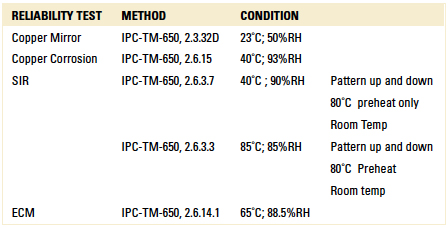
    Second, the flux chemical package is formulated to minimize the impact of unavoidable spreading and splashing events. These will result in partially heated flux residues, which won’t be removed by the washing action of the solder. As such, they pose a serious threat to assembly reliability, as ionic residues can induce electrochemical migration, corrosion and resistance losses, which could result in the in-field failure of the assembly when exposed to a moist environment.2,3 It is therefore of paramount importance to establish a correlation of the thermal history of the flux with the reliability of the residues. From this perspective, a series of activator packages has been designed specifically to guarantee an optimal reliability when partially heated.4 The reliability of the fluxes designed for the selective soldering application was assessed using common industry standards, where the flux was subjected to various thermal conditioning (TABLE 1).
    TABLE 1. Flux Reliability Testing Methods
    kesterTable1

    A statistically significant experimental protocol was conducted on Ersa selective soldering equipment to evaluate the impact of materials and process parameters on the following response factors: dispensing performance (clogging and satellites), flux spread and soldering performance. The results of these experiments are reported in the following paragraphs.
    Flux spread. Flux spread is influenced by the surface tension of the flux and its temperature.  Alcohol-based fluxes have a much lower surface tension than VOC-free fluxes, which are water-based (22mN/m at 25˚C vs. 72mN/m). Also, the dispensing temperature will tend to favor spreading by lowering the flux viscosity.

    On the other hand, the impact of the board preheat will depend on the nature of the flux; VOC-free fluxes tend to spread more on warmer boards, while an alcohol-based board will show an opposite trend as the temperature thinning effect competes with the high drying rate of the flux. Finally, the surface energy of the solder mask is another critical parameter; lower surface energies are favored for selective soldering fluxes compared with conventional wave soldering fluxes (35mN/m vs > 50mN/m) to increase the contact angle of the flux on the substrate. This is easily understood when looking at the balance of surface
    tensions modeled in Young’s equation: γSG=γSL+γLGcosθ. It should be noted preheating the board may impact the surface energy of the solder mask.

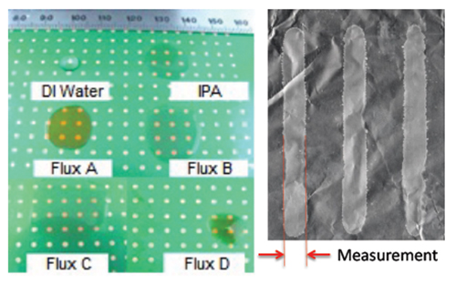
    We estimate the intrinsic spreading of fluxes by deposition on a representative set of PCBs with various solder mask types. In contrast, in-process optimizations of the flux spread are conducted by directing the drop jet on the shiny side of an aluminum foil, which presents a comparable surface energy, and measuring the dried deposits after preheat as illustrated in FIGURE 1.
    kester1
    FIGURE 1. Flux spread measurement (Left: PCB; right: Al foil).
    Drop jet dispense: clogging and satellites. High-frequency drop jet technology has been developed to narrow the spray pattern compared to atomizing-type aerosol spray heads or ultrasonic spray fluxers. The deflection of the flux droplets is minimized, but occurrence of satellites is always a possibility; these very small flux droplets varying in sizes appear in random directions outside of the flux direct deposition corona. They depend on the flux physicochemical characteristics (viscoelastic properties, surface tension), hence its formulation, coupled with the jetting process itself. It is critical to mitigate the formation of satellites, as these side deposits won’t be exposed to the same heat cycle and solder scrubbing mechanism as non-deflected droplets, and will therefore pose a serious threat of electrochemical migration under bias in a moist environment.

    Another processing issue frequently encountered during dispense is the clogging of the drop-jet fluxer, as a result of the narrow channels of the spray head (typically 130µm) combined with the high-volatility of alcohol-based selective soldering fluxes.

    Both clogging and satellite formation are assessed during the same set of experiments, which enable us to screen our flux formulation efficiently on industrial selective soldering equipment. Fax paper is used to identify the location of the geometry of droplet deposits. It should be noted that use of fax paper for in-process spread measurement is typically avoided, as the absorption of flux into the fabric of the substrate will result in an inaccurate representation of the flux spread data.

    The tests consist of successive deposition cycles executed at increasing time intervals. Twenty dots are printed at 2 sec. intervals in one cycle. This sequence is repeated four times, with 30 sec. breaks between each cycle. The whole procedure is then repeated four times, this time with 15 min. breaks in between. The dot geometries and satellite positions are computed for the 500 dots deposited in total using image analysis software. The successive breaks during the sequence make the procedure particularly aggressive. In our experience, a continuous flow of flux through the drop jet unit self-regenerates the head, while the breaks give time for the deposits to accumulate, ripen and create solid deposits on the side, which are more difficult to remove when the sequence is restarted. In consequence, fluxes can be efficiently discriminated through this experimental protocol.

    FIGURE 2 shows a representative set of deposition patterns obtained with various fluxes: the flux #2 deposition conditions were near perfect, while #10, #6 and #13 show multiple defects. Observe that satellites and variations in surface area of the deposit often happen at the beginning of the sequence, where
    deposit concentration is at its maximum, which demonstrates this effect is the major root cause for dispensing failures.
    kester2
    FIGURE 2. Typical deposition patterns for the drop jet dispensing test.

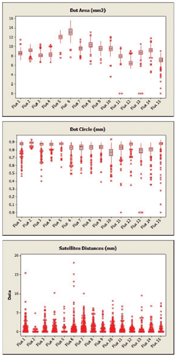
    Overall, 15 formulas were screened using the statistically significant set of data generated during these complex  deposition sequences. Results of the deposition pattern analysis are reported in FIGURE 3. The efficiency of this screening method is confirmed, as large differences are observed between fluxes, in terms of uniformity of the deposits across the whole deposition sequence (dot area and dot circle), as well as the occurrence and spatial distribution of the satellites. Fluxes #1, 2, 3 and 4 present the best dispensing performance and were selected for the final soldering performance assessment.
    kester3
    FIGURE 3. Dispensing test results for 15 experimental formula. Statistical analysis of 500 data points per formula, collected through an image analysis software.
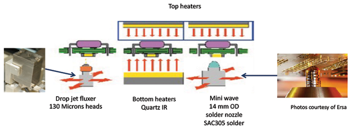
    Soldering performance. A performance evaluation was completed on an industrial selective wave soldering machine from Ersa (FIGURE 4), using 93 mil FR-4 boards made of four copper layers (1/2/2/1 oz.), solder mask over bare copper (SMOBC) and an OSP finish (FIGURE 5).
    kester4
    FIGURE 4. Selective soldering equipment configuration.
    kester5
    FIGURE 5. Selective soldering testing board.
    These boards were populated with 16-pin dual inline packages (DIPs) containing IC chips and 96-pin Eurocard connectors.

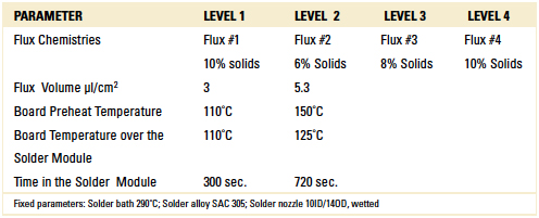
    To determine the soldering performances of the fluxes, the L16 Taguchi design of experiment reported in TABLE 2 was used.  
    TABLE 2. Soldering Performance DoE parameters
    kesterTable2

    The response factors were flux spread (measured area), % hole fill (evaluated by x-ray diffraction), and the number of solder bridges and solder balls (visual count).
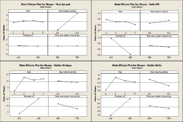
    The statistical analysis of the results is reported in FIGURE 6. Main effects are represented here, as second-order interactions were found to be statistically insignificant.
    kester6
    FIGURE 6. Soldering performance DoE results.

    All fluxes presented similar spreading results, the only impactful process parameter being the dispensed volume. Hole fill performance was found to be comparable between fluxes, while particular attention needs to be given to the board preheat temperature. This result is in good agreement with our background knowledge.  Preheat times are relatively long in point-to-point selective soldering applications, which poses a challenge to the thermal stability of the activator packages. In this context, very satisfactory performance is found with all fluxes for a preheat temperature of 110˚C. More flux discrimination was found when considering soldering defects. Flux #1 clearly stands out compared with the three other fluxes, with minimal defect rates observed in all conditions. The strong impact of board preheat temperature on defects confirms our initial interpretation on the activators’ thermal stability envelope.

    Conclusion
    The design of high-performance fluxes for selective soldering applications requires a combination of formulation, application and equipment expertise that mandates a strong partnership between flux designer and equipment manufacturer. Multiple performance aspects have to be taken into account. The flux itself must have proven reliability (corrosion, electrochemical migration) under various heat exposure conditions, in particular when only partially activated. Having down-selected a series of fluxes filling this requirement, it is necessary to conduct statistically designed experiments on industrial wave soldering machines to map the relationships between flux characteristics and selective process friendliness. In this area, multiple performance attributes are considered: compatibility with drop jet dispensing (clogging effects, cleaning frequency, and satellite formation), spreading on the board (in actual processing conditions, with multiple solder resist types) and soldering performance (fluxing activity, thermal stability) as measured by barrel filling and defect production.
    2

    查看评论

  3. Open any magazine and it’s clear that applications for 3D printing are exploding. Yet one area that remains largely unexplored is the use of additive manufacturing for electronics. The convergence of electronics and 3D printing will have staggering implications for the electronics industry—particularly around printed circuit boards and rapid prototyping.

    Not surprisingly, the 3D printed electronics space is in its infancy, more or less at the same level of adoption as regular 3D prototyping was in 2009. But its slow adoption is not from a lack of interest or need; rather, it’s because creating 3D printers for PCBs is exceedingly complex and existing inks and printers just weren’t up to the challenge. These printers must be able to print conductive traces, which is the domain of printed electronics and produce components that meet the demanding performance requirements of aerospace, defense, consumer electronics, Internet of Things and even wearables.

    Printer nuances
    Certainly, there already are some 3D printers capable of including some conductive traces by embedding basic wiring by extruding of conductive filaments. The end result of these types of printing techniques is a low-resolution, point-to-point conductive trace that may be suitable for hobbyists but not for professional electronics. Higher resolution and higher conductivity that meets the needs of professional electronics requires more advanced printing solutions and materials.

    Other actual conductive circuit printer systems are available today. They are designed to print conductive traces on one and sometimes both sides of a substrate, creating two-sided PCBs. These printed electronics are not the same as 3D printed electronics, however, which builds up a PCB on a substrate with layer after layer of material, creating a true multi-layer, interconnected, 3D-printed circuit board. To 3D-print electronics requires advanced materials and highly specialized equipment.

    3D printers and materials for PCBs
    Developing systems for true 3D-printed electronics involves creating exceedingly precise hardware with three axes: X, Y and Z. It also requires using specialty inks that are engineered at the nanoparticle level. The final element needed is advanced software that ties it all together, including the ability to effortlessly convert standard PCB Gerber design files—which are designed for 2D manufacturing environments—into 3D printable files. This allows for the 3D printer to print the substrate to the required thickness, leave and fill holes where vias are required, and more. Software for the design and validation of freeform circuit geometries isn’t yet readily available in the marketplace but will open up further electronics design abilities.

    Still, despite the complexities of building such 3D printers, the benefits of using them are obvious for electronics and other industries. PCB designers and electronics engineers are eager for the first 3D printers for professional printed electronics to emerge. My company will answer that call when the Nano Dimension DragonFly 2020 3D Printer, which we’ve been demonstrating at shows including CES 2016, becomes available commercially later this year. It is anticipated to be the first entrant into this new class of high resolution enterprise 3D printers.

    Practical uses and benefits for prototyping
    Interest in these highly specific 3D printers is very high. The possibility of using additive manufacturing to create professional PCBs offers manufacturers the flexibility of printing their own circuit board prototypes in-house for rapid prototyping, R&D, or even for custom manufacturing projects. While it is unlikely that 3D printers for electronics will replace all of the traditional processes for in-house development of high-performance electronic device applications, they will be particularly useful for prototyping, reducing time to build from weeks to just hours.

    Manufacturers adopting this new technology can expect a variety of gains, including cutting their time to market with new products and speeding iterations and innovation around PCBs. With a 3D PCB printer, they can even build and test PCBs in sections if they’d like.

    For many, one of the most exciting developments with this technology is that they will no longer need to send out their intellectual property to be manufactured off-site by specialist sub-contractors—which essentially puts their IP at risk. For others, the promise of rapid prototyping, significant reductions in the development costs and increased competitive edge are the most important benefits.

    But perhaps most importantly, 3D printing for circuit boards offers nearly limitless design flexibility.


    A PCB printed on a Nano Dimension 3D printer

    With traditional PCB prototyping, turnaround times of weeks or even months for multiple iterations while perfecting a design can wreak havoc on time-to-market. Given that, many designers opt for more conservative designs. Printing the PCB prototypes in-house means designers can risk being more creative without slowing the development process.

    Also, manufacturing currently requires multiple specialized (and expensive) techniques, such as precision drilling, chemical etching, plating, pressing and lamination. These techniques, which are usually outsourced to companies in Asia, could all be done easily with in-house 3D printing in just hours, even when the PCB has multiple layers and many interconnects.

    3D printing of PCBs will help to keep up with the changing needs of customers who require device miniaturization and customization.


    Continue reading at EE|Times. 
    0

    添加评论

  4. Based on discussions at DesignCon 2016 and since, I have three predictions about major changes ahead for high speed serial link systems.
    Roll out of 28 Gbps systems will be slower than expected.
    I hear that the semiconductor companies producing the CMOS devices—ASIC, FPGA or custom—are doing fine producing the silicon with acceptable performance at 28 Gbps. Figure 1 is an example of a very clean eye from a 28 Gbps TX (transmitter).
    Figure 1. Today's silicon can product clean signals at 28 Gbps, at least at the transmit end.
    Semiconductor manufacturers' ability to sell to end users designing and manufacturing systems operating with 28 Gbps links is, however, limited by the their ability to support these customers.
    A link operating at 28 Gbps, NRZ (non-return-to-zero), has to be designed with everything working almost perfectly. This data rate pushes the limits such as: low Df materials, smoother copper, wide enough lines, equalization tuned to the limit of recovering -25 dB of insertion loss, minimal reflections, via stubs shorter than 15 mils, channel-to-channel cross talk less than -50 dB, and line-to-line skew less than 6 ps over as long as 20 in.
    By themselves, each item is possible to engineer, but all of them at the same time in the same channel requires solid engineering and analysis. Not every design team is capable of this task. When the channel does not work, who do they call? The silicon provider.

    I hear that with a limited number of experienced support application engineers, the silicon providers are focusing on their large, high-end OEM customers and are limiting their sales based on which customers they have the resources to support. This may be a business opportunity for consulting engineering teams to work with silicon providers to support their customers and increase the design wins and sales of 28 Gbps capable silicon.
    There is a potential roadblock ahead for 56 Gbps PAM4 systems.
    A number of channels have been demonstrated operating at 56 Gbps with PAM4. The picks and shovels needed for PAM4 systems are in place. Most of the high-end software vendors have shown design tools for simulating PAM4. All the high-end oscilloscope and BERT (bit-error-rate tester) manufacturers have shown instruments able to measure and characterize PAM4 systems.Figure 2 shows the measured eye for a 56 Gbps PAM4 link.
    Figure 2. At the transmitter, a PAM4 signal is clean enough for all three eyes to be visible.
    It's widely believed that the advantage of going to PAM4 for 56 Gbps is so that we are only dealing with signals with an equivalent bandwidth of 28 Gbps signals. If we can design a channel for 28 Gbps at PAM2, we should be able to design one for 56 Gbps at PAM4.
    Not so fast, for there is one significant difference with PAM4. By dividing up the signal into three levels plus zero, we dropped the signal level for one bit by 1/3. The signal voltage level we have to measure is smaller. If we need a particular SNR (signal-to-noise ratio) at the receiver for an NRZ-PAM2 signal, and the signal level dropped by 10 dB, the acceptable noise level has to drop by 10 dB in PAM4. But wait, we're not done.
    In NRZ-PAM2, we need about -50 dB isolation between a channel and all other aggressors for a SNR of 20 dB. With a lower noise floor required in PAM4, this means an isolation of –60 dB. When it comes to cross talk, we still have high level signals corresponding to the fourth bit level sometimes coming out of the TX. This means the signal on the aggressor can be 3x higher than the signal of the second bit. To keep the same noise on the victim line when the aggressor has 10 dB higher strength, we need another 10 dB more isolation. This means an isolation of as low as -70 dB between the victim channel and all other aggressor channels.
    I hear that the weak link in achieving this low level of isolation is in the via field under the BGA. At this low level of crosstalk required, issues such as differential to differential coupling in the via field under the BGA and common noise to differential noise conversion in all via fields, in connectors and in channel to channel cross talk, can be showstoppers. While it may be possible, with good engineering practices and optimized pad stack design to reduce cross talk to the -50 dB level, getting to -70 dB is a major engineering effort.
    At this level, as well designed as a via area is, manufacturing variations in the fabricated board can push a system into too much cross talk.
    There are some fundamental limitations to what can be done at the board level if the package footprint is poorly designed. This puts a larger burden on the silicon providers to design the package footprint with channel to channel cross talk at the board level via field in mind. This does not play to their strengths.
    While getting one channel operating at 56 Gbps PAM4 is possible, getting hundreds of channels operating, in close proximity, at acceptable bit error ratio, maybe require heroic efforts.
    All is not doom and gloom
    I did hear of one innovation that may be the savior for high-speed serial links in copper-based interconnects. Given the increasing challenges to get a long channel operating at 28 Gbps in PAM2-NRZ or a 56 Gbps channel operating at PAM4, there may be an intermediate fix available. Every large connector company I spoke with has a practical plan to implement cabled interconnects integrated with the board to supplement laminated backplane and motherboard routing.
    The advantage of a cabled system is lower loss and less channel-to-channel cross talk. The larger circumference in the round conductors means lower conductor loss per length in a cable than on a board. While there may be lower cross talk in the cable interconnects, the cross talk in the connector and its board footprint still needs to be considered, but many of the connector companies seem very good at this.
    These solutions involve a connector system to mate between the board and an array of cables and back to the board. The idea is to route long distance, high bandwidth signals off the board, through cables and then back to the board. Figure 3 shows an example: the Firefly product from Samtec. A nice feature of the Samtec system is the integration of optical cables as well as copper cables to ease the transition to board-level optical interconnects.
    Figure 3. Samtec's Firefly interconnect system merges optical and electrical connections to improve signal integrity.
    This sort of approach, with a much lower loss at 14 GHz and 28 GHz, maybe the short-term fix to enable both a robust 56 Gbps (28 Gbaud) PAM4 or an PAM2-NRZ 56 Gbps system without the headaches of extremely high isolation requirements of a PAM4 system.
    This sort of backplane architecture moves the interconnect roadmap onto a different trajectory and may give additional headroom to copper interconnects into the next generation of data rates. With the option of also including fiber optics, it may be the “gateway drug” into the long touted optical backplane architecture of the future.
    Editor:
    0

    添加评论

  5. When we create a printed circuit board, the chances are these days that we’ll export it through our CAD package’s CAM tool, and send the resulting files to an inexpensive PCB fabrication house. A marvel of the modern age, bringing together computerised manufacturing, the Internet, and globalised trade to do something that would have been impossible only a few years ago without significant expenditure.
    Those files we send off to China or wherever our boards are produced are called Gerber files. It’s a word that has become part of the currency of our art, “I’ll send them the Gerbers” trips off the tongue without our considering the word’s origin.
    This morning we’re indebted to [drudrudru] for sending us a link to an EDN article that lifts the lid on who Gerber files are named for. [H. Joseph Gerber] was a prolific inventor whose work laid the ground for the CNC machines that provide us as hackers and makers with so many of the tools we take for granted. Just think: without his work we might not have our CNC routers, 3D printers, vinyl cutters and much more, and as for PCBs, we’d still be fiddling about with crêpe paper tape and acetate.
    An Austrian Holocaust survivor who escaped to the USA in 1940, [Gerber] began his business with an elastic variable scale for performing numerical conversions that he patented while still an engineering student. The story goes that he used the elastic cord from his pyjamas to create the prototype. This was followed by an ever-more-sophisticated range of drafting, plotting, and digitizing tools, which led naturally into the then-emerging CNC field. It is probably safe to say that in the succeeding decades there has not been an area of manufacturing that has not been touched by his work.
    So take a look at the article, read [Gerber]’s company history page, his Wikipedia page, raise a toast to the memory of a great engineer, and never, ever, spell “Gerber file” with a lower-case G.
我的简介
我的简介
博客归档
正在加载
“动态视图”主题背景. 由 Blogger 提供支持. 举报滥用情况.